Draw N Stage Circuit Diagram Of Impulse Voltage Generator

Igbts Frequently Asked Questions Faqs Power Electronics
Impulse Test Of Transformer Electrical4u
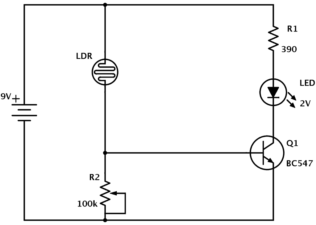
Ldr Circuit Diagram Build Electronic Circuits

Electromagnetic Coil Gun

A Photograph Of The Four Channel Generator Of Modulated Rf Pulses Download Scientific Diagram
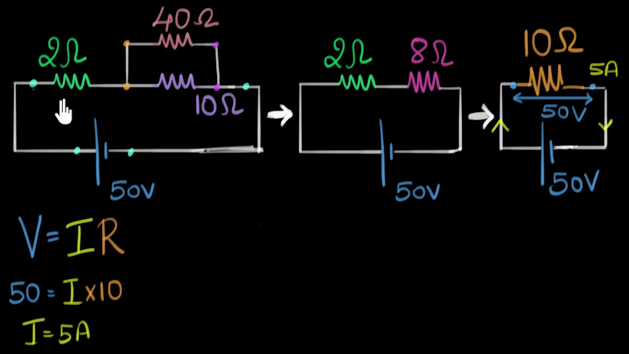
Solved Example Finding Current Voltage In A Circuit Video Khan Academy
Questions related to circuit elements If you're seeing this message, it means we're having trouble loading external resources on our website If you're behind a web filter, please make sure that the domains *kastaticorg and *kasandboxorg are unblocked.

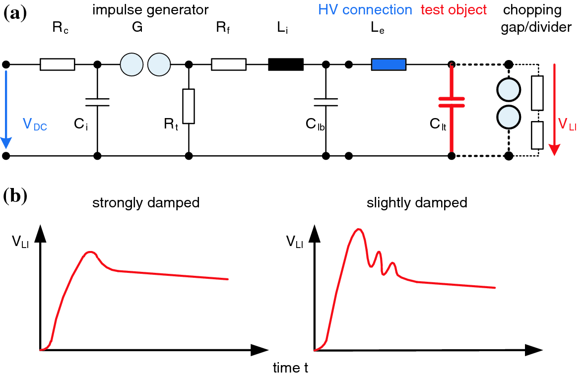
Draw n stage circuit diagram of impulse voltage generator. 27 a) Circuit diagram and b) a snapshot of the multiple chopping gap Courtesy of Manitoba Hydro HVTF a) High voltage winding diagram with CT connections and tap changer positions, b) Low voltage winding diagram, c) Plan view of the high voltage, low multistage impulse generator is simplified to a single stage generator The DUT’s. The point at which the zener voltage triggers the current to flow through the diode can be very accurately controlled (to less than 1% tolerance) in the doping stage of the diodes semiconductor construction giving the diode a specific zener breakdown voltage, ( Vz ) for example, 43V or 75V This zener breakdown voltage on the IV curve is. Which is from a single phase line and a generator used for measuring and comparing the supply, it then base its control operation on voltage level of the utility supply with a set the.
In the basic circuit, a source may be dc or ac, and its internal resistance (R i) or generator output impedance (Z g) drives a load resistance (R L) or impedance (Z L) (Fig 1) R L = R i or Z L = Z g. The voltage can be blocked by removing the stored voltage This looks as a surplus current added to the load current which is called as the reverse recovery current of the diode ‘Irr’ The max of Irr occurs (di/dt = 0) when the amount of the sudden voltages through the IGBT & the diode matches the supply voltage. Iv sampling mixer has been developed along with the design of the strobe pulse generator appropriate for the impulse radar system The integrated sampling mixer has.
The LSS6110 simulator, like the LSS6230 mentioned in Section 44, is a combination wave generator or hybrid generator that can provide a 12/50 μs impulse voltage in an open circuit (12 μs corresponds to the front time and 50 μs corresponds to the time to halfvalue as depicted Fig 52) and an 8/ μs impulse current in a short circuit (8 μs front time and μs time to halfvalue. This is just a few minutes of a complete course Get full lessons & more subjects at http//wwwMathTutorDVDcomIn this lesson the student will learn what. Open a new blank model to contain your first circuit and save it as circuit1 Add the AC Voltage Source block from the Simscape > Electrical > Specialized Power Systems > Fundamental Blocks > Electrical Sources library Set the Amplitude, Phase, and Frequency parameters of the AC Voltage Source block according to the values shown in Circuit to Be Modeled.
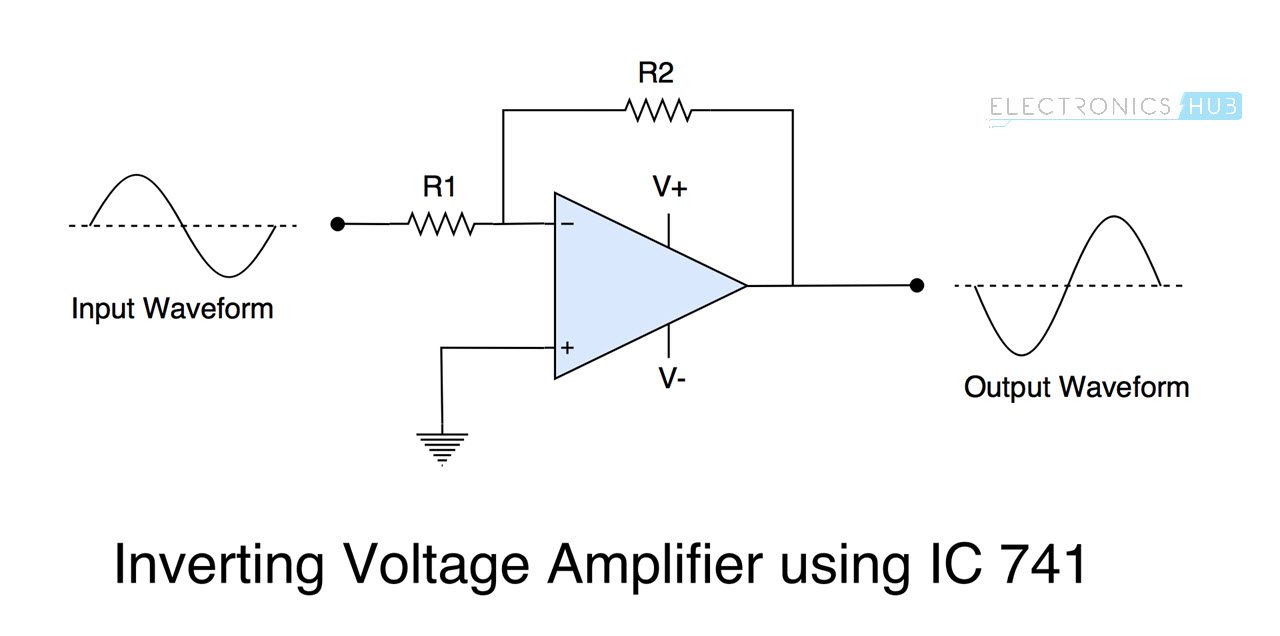
A circuit diagram (electrical diagram, elementary diagram, electronic schematic) is a graphical representation of an electrical circuitA pictorial circuit diagram uses simple images of components, while a schematic diagram shows the components and interconnections of the circuit using standardized symbolic representations The presentation of the interconnections between circuit components in. Whilst I might succumb in my crazier evangelical moments to the idea that academic authors (other than those who speak LateX natively) and media developers might engage in the raw circuitikz authoring described Reproducible Diagram Generators – First Thoughts on Electrical Circuit Diagrams, the reality is that it’s probably just way too clunky, and a little bit too far removed from the. Where ω = 2πƒ and the output voltage Vout is a constant 1/RC times the integral of the input voltage V IN with respect to time Thus the circuit has the transfer function of an inverting integrator with the gain constant of 1/RC The minus sign ( – ) indicates a 180 o phase shift because the input signal is connected directly to the inverting input terminal of the operational amplifier.
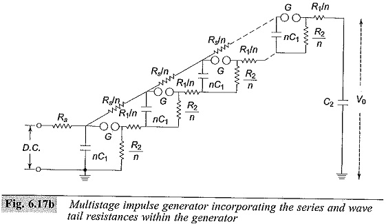
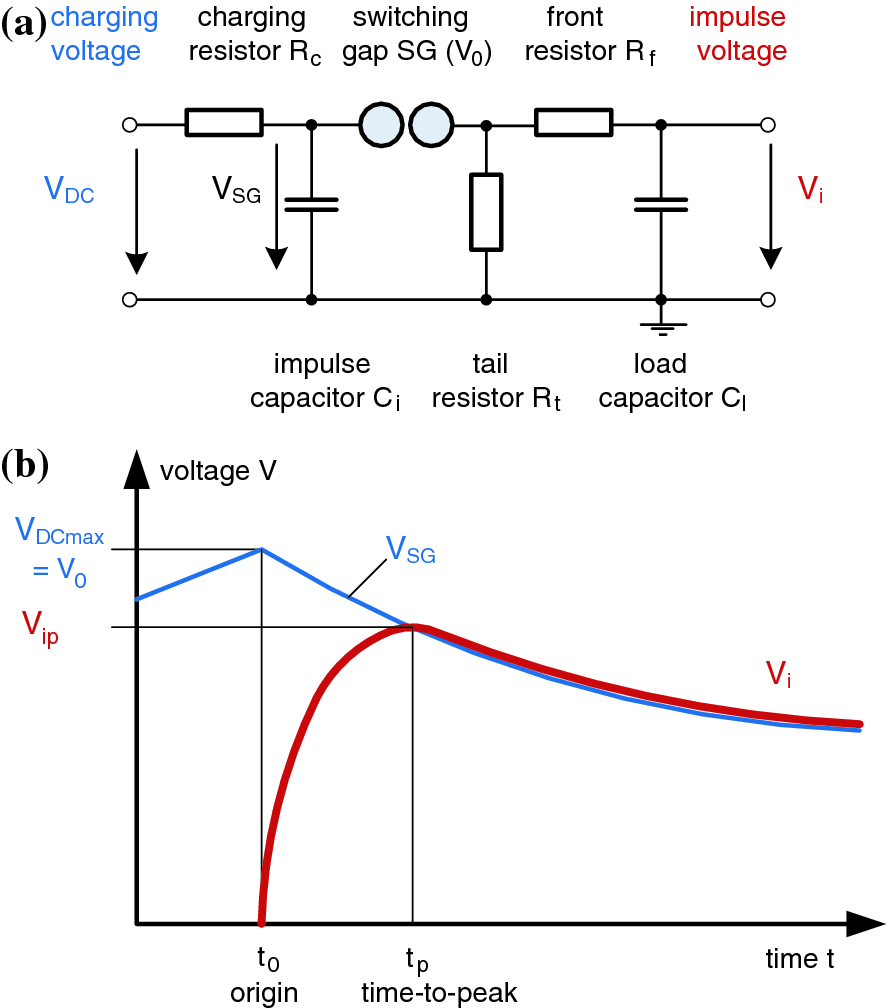
A voltage to current (VI) converter accepts as an input a voltage Vin and gives an output current of a certain value In general the relationship between the input voltage and the output current is Iout =SVin (118) Where S is the sensitivity or gain of the VI converter Figure 7 shows a voltage to current converter using an opamp and a. 15 Schematic circuit diagram for automatic transfer switch 16 Recommended cable size Generator Running 1 NO, Load on Generator 1 NO, Load on Main 1 NO Rated impulse withstand voltage, Uimp 8kV AC rated operational current *(1). Impulse voltage generator circuits The introduction to the full impulse voltages as defined in the previous section leads to simple circuits for the generation of the necessary wave shapes The rapid increase and slow decay can obviously be generated by discharging circuits with two energy storages, as the wave shape may well be composed by the.
The 10k pot in the circuit doesnt adjust the voltage, but I realize voltage can be adjust from the 100k pot i used at the 4047 and for the 180k resistor I used a 250k pot and set the value to 180k but moving it around also changes the voltage but not the 10k pot and the main prob is the frequency, I also tried a 12v half amp transformer it. For example, here is the schematic diagram for a CMOS NAND gate Notice how transistors Q 1 and Q 3 resemble the seriesconnected complementary pair from the inverter circuit Both are controlled by the same input signal (input A), the upper transistor turning off and the lower transistor turning on when the input is “high” (1), and vice versa. Electric potential diagrams were introduced in Lesson 1 of this unit and subsequently used to illustrate the consecutive voltage drops occurring in series circuits An electric potential diagram is a conceptual tool for representing the electric potential difference between several points on an electric circuit.
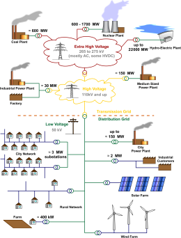
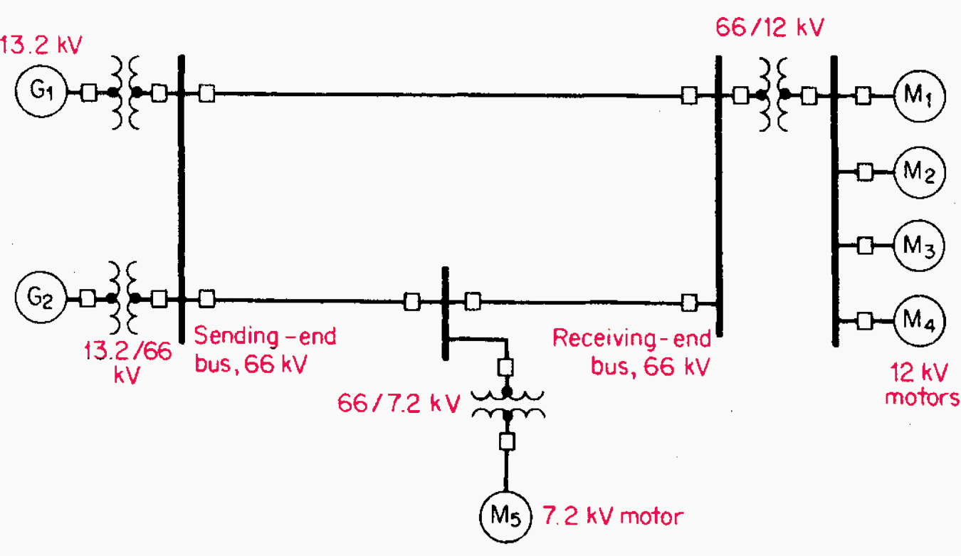
Single line diagram is the representation of a power system using simple symbols for each component The single line diagram of a power system is networked show the main connections and arrangement of the system components along with their data (such as output rating, voltage, resistance and reactance, etc). USB2 US11/675,354 USA USB2 US B2 US B2 US B2 US A US A US A US B2 US B2 US B2 Authority US United States Prior art keywords dtp clock iir input fir Prior art date Legal status (The legal status is an assumption and is not a legal conclusion. The frequency of the input voltage thus determines the height of the output voltage RC bandpass – how it works The RC band pass works through the composition of high pass and low pass filters as well as these two elements In the highpass section, the voltage across the resistor is tapped, with the lowpass over the capacitor.
Open a new blank model to contain your first circuit and save it as circuit1 Add the AC Voltage Source block from the Simscape > Electrical > Specialized Power Systems > Fundamental Blocks > Electrical Sources library Set the Amplitude, Phase, and Frequency parameters of the AC Voltage Source block according to the values shown in Circuit to Be Modeled. The circuit does not draw current when the lamps are off, so it may be battery powered with no additional cutoff switch use at least 2u of electrolytics and 100n ceramic caps near the transistors on both circuits (the output stage needs them on _both_ supplies) 'Nixie' display tubes Simple High Voltage Generator 12 V in, 12,000 V. I am designing a voltage multiplier circuit I started off by building a 2stage half wave voltage multiplier circuit using NTE517 (5kV) diodes and 1000pF (15kV) capacitors I connect the circuit to a variable transformer and tuned the variable transformer to 10Vac My result for my 1st stage is 557Vdc and 2nd stage is 372Vdc.
Was achieved by using voltage monitoring relay (VMR) as a primary component of the The ATS monitors the supply of voltage power sensing and control circuit;. Functioning at 1 KHz or higher frequency, the pulse generator demonstrated below drives a voltage doubler circuit furnishing a negative potential getting close to that of the positive input supply Using a 10 volt input, an output of around 9 VDC has been measured into a ,000 ohm load. 13 Impulse Generator and Equipment The Impulse Generator used in the testing was a Hipotronics™ Series 100 It is a threestage generator resulting in a peak capability of 300kV The control system installed as part of the impulse generator is a Hipotronics™ model 970IGDS, and is a programmable digital design An impulse generator has two.
An impulse generator circuit accordi ng to the input data of the table II was implemented a s an energizer prototype, using the design procedure presented (Fig 12). 25 Full PDFs related to this paper READ PAPER Electrical Engineering question and answers. A voltage to current (VI) converter accepts as an input a voltage Vin and gives an output current of a certain value In general the relationship between the input voltage and the output current is Iout =SVin (118) Where S is the sensitivity or gain of the VI converter Figure 7 shows a voltage to current converter using an opamp and a.
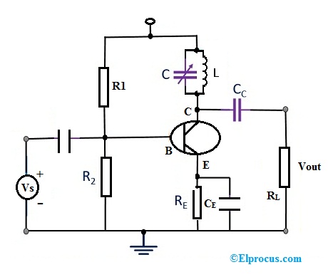
Fig 81 Generator Regulator If the voltage is less than 77 volts, check for excessive resistance in the solenoid control circuit If the voltage exceeds 77 volts, remove the start ing motor and check (1) solenoid current draw, (2) starting motor pinion clearance, and (3) free dom of shift lever linkage 2. Common Emitter Amplifier Circuit Diagram In this kind of biased, the transistor will reduce the current amplification effect factor ‘β’ by holding the base bias on a constant steady voltage stage & permits precise stability The Vb (base voltage) can be measured with the potential divider network. Voltage monitoring circuit for 12 volt lipo battery pack schematic circuit diagram TD293 100W RMS AMPLIFIER SCHEMATIC CIRCUIT DIAGRAM PS1502D 015V ADJUSTABLE 15V 72V STAGE POWER SUPPLY SCHEMATIC CIRCUIT DIAGTRAM.
So how does it work The circuit shows a half wave voltage doubler During the negative half cycle of the sinusoidal input waveform, diode D1 is forward biased and conducts charging up the pump capacitor, C1 to the peak value of the input voltage, (Vp)Because there is no return path for capacitor C1 to discharge into, it remains fully charged acting as a storage device in series with the. Whilst I might succumb in my crazier evangelical moments to the idea that academic authors (other than those who speak LateX natively) and media developers might engage in the raw circuitikz authoring described Reproducible Diagram Generators – First Thoughts on Electrical Circuit Diagrams, the reality is that it’s probably just way too clunky, and a little bit too far removed from the. Was achieved by using voltage monitoring relay (VMR) as a primary component of the The ATS monitors the supply of voltage power sensing and control circuit;.
1 Singleline diagrams (SLD) A singleline diagram shows the disposition of equipment in a substation, or network, in a simplified manner, using internationally accepted symbols to represent various items of equipment such as transformers, circuit breakers and disconnectors, generally with a single line being used to represent threephase connections. 1 Singleline diagrams (SLD) A singleline diagram shows the disposition of equipment in a substation, or network, in a simplified manner, using internationally accepted symbols to represent various items of equipment such as transformers, circuit breakers and disconnectors, generally with a single line being used to represent threephase connections. One of the simplest ways to make a battery powered High Voltage power supply is to use a common car ignition coil Ignition coils are a type of induction transformer based on the Tesla Coil invented by Nikola Tesla in 11 The voltage rise is not given by the turns ratio like in a standard transformer, but is proportional to the rate of change of current in the primary circuit.
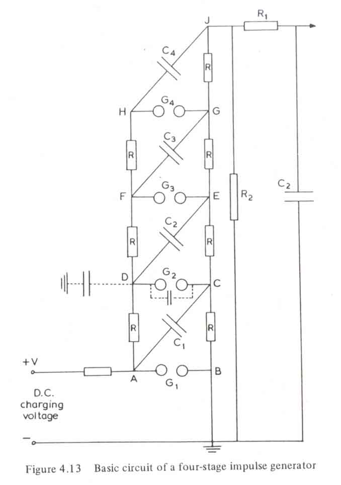
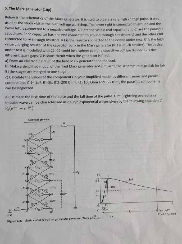
Draw a circuit diagram of a simple voltage doubler Fig31 Voltage Doubler Circuit 7 Write the expression to find the optimum number of stages and %ripple in a voltage multiplier A 12 stage impulse generator has a 0126µF capacitor The wave front and wave tail resistances. An impulse voltage generator of n stages An impulse voltage generator without steeping circuit, operating without front resistors, can generate impulse voltages with front times down to about 100 ns Fig 725 a Simplified block diagram of a singlestage SI generator. Which is from a single phase line and a generator used for measuring and comparing the supply, it then base its control operation on voltage level of the utility supply with a set the.
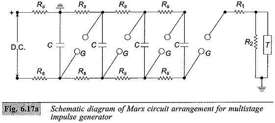
The figure shows an equivalent circuit diagram for a single stage impulse generator (it ispossible to simplify a multi stage impulse generator into this circuit) Design CDY series impulse generator is based on the MARX multiplier circuit The construction of SGV generators is the result of decades of experience in designingimpulse test systems. Functioning at 1 KHz or higher frequency, the pulse generator demonstrated below drives a voltage doubler circuit furnishing a negative potential getting close to that of the positive input supply Using a 10 volt input, an output of around 9 VDC has been measured into a ,000 ohm load. SmartDraw is the easiest circuit diagram maker on the market today Here's how it works Open an wiring diagram or circuit drawing template—not just a blank screen Add circuit symbols, switches, relays, and more SmartDraw circuit drawing software works with you instead of against you.

Marx Generator Wikipedia
Distribution Voltage Level An Overview Sciencedirect Topics
Electric Power Distribution Wikipedia

Consulting Specifying Engineer How To Optimize Electrical Systems From Design To Commissioning
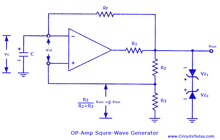
Square Wave Generator Using Op Amp

Impulse Voltage Generator Circuits
Generation Of High Voltages In The Lab Ac Dc Switching Lightning Impulse
Q Tbn And9gcsh5nml2oayzowhkui8xgm1j Jrowyyskn4gjbnksvieojilxxu Usqp Cau
Multistage Impulse Generator Circuit Marx Circuit Components
Transformers Physics
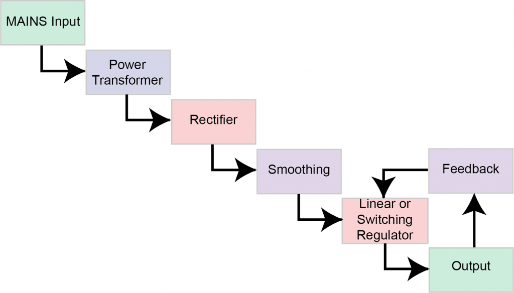
Regulated Power Supply Block Diagram Circuit Diagram Working
Single Tuned Amplifier Circuit Diagram Operation And Its Applications
Www Nrc Gov Docs Ml1122 Mla143 Pdf

Pdf Multi Purpose Low Cost Dc High Voltage Generator 60kv Output Using Cockcroft Walton Voltage Multiplier Circuit
Pulse Marx Generator

Basic Circuit Of Single Stage Impulse Generator Download Scientific Diagram

National Grid Power Supply Electricity Explaining Use Of Transformers Formula Theory Calculations Pylons Versus Underground Cables Igcse Gcse Physics Revision Notes
Three Phase Inverter Circuit Diagram 1 Degree And 180 Degree Conduction Mode
Tests With High Lightning And Switching Impulse Voltages Springerlink
Generation Of Impulse Currents Waves Definition Circuit Diagram
Power Supply Basics Wavelength Electronics
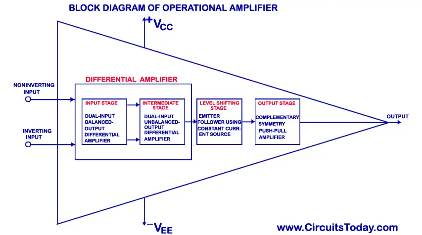
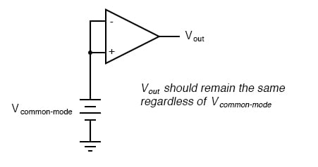
Operational Amplifier Op Amp Basics Ideal Op Amp Working Inverting Non Inverting Op Amp
Tests With High Lightning And Switching Impulse Voltages Springerlink
Q Tbn And9gcqalza2z9mu2xb1iqd2byd3b Quztq7 Fhvvgjamheupde0lrz7 Usqp Cau

Voltage Multiplier Wikipedia
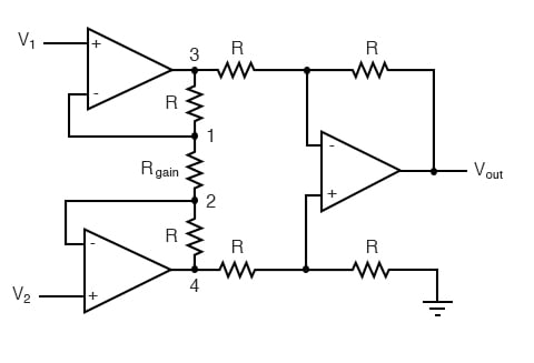
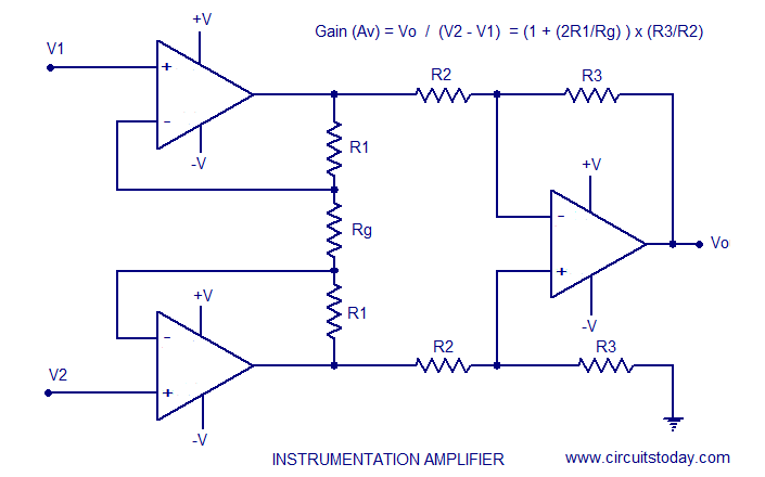
The Instrumentation Amplifier Operational Amplifiers Electronics Textbook

Cockroft Walton Voltage Multiplier Circuit Generation Of High Voltages And Currents
Pdf Multi Purpose Low Cost Dc High Voltage Generator 60kv Output Using Cockcroft Walton Voltage Multiplier Circuit

Op Amp Integrator Operational Amplifier Integrator
High And Low Voltage Cut Off With Time Delay Circuit Diagrams Schematics Electronic Projects

Impulse Voltage Generator Circuits

Electrical Grid Wikipedia
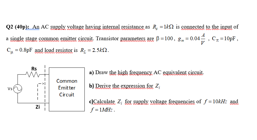
Solved Q2 40p An Ac Supply Voltage Having Internal Res Chegg Com

Pdf Multi Purpose Low Cost Dc High Voltage Generator 60kv Output Using Cockcroft Walton Voltage Multiplier Circuit

Voltage Regulator Wikipedia

Impulse Test Of Transformer Electrical4u
Generation Of High Voltages In The Lab Ac Dc Switching Lightning Impulse

Impulse Voltage Generator Circuits
2
3 Draw A Single Line Diagram Of A Generation Tra Chegg Com
Rlc Series Ac Circuits Physics

Ac Dc Converters Including Buck Boost And Flyback
Cockcroft Walton Voltage Multiplier Circuit Generator
How To Calculate And Draw A Single Line Diagram For The Power System Eep
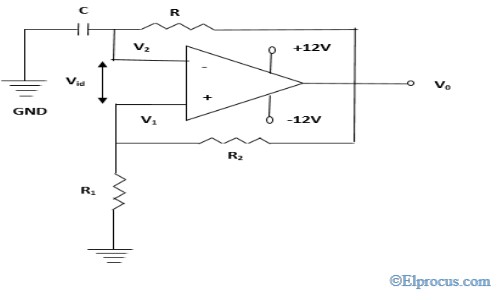
Square Wave Generator Circuit Diagram And Its Advantages
Q Tbn And9gcrvkyanc2oyayzglt5yekxok0pvkzxxp Qmebj6qm6x9f4lxky6 Usqp Cau

Common Emitter Amplifier And Transistor Amplifiers

Series Resonant Circuit Generation Of High Voltages And Currents

Basic Circuit Of Single Stage Impulse Generator Download Scientific Diagram

Impulse Voltage Generator Marx Generator Circuit Diagram Working Principle And Applications

Impulse Voltage Generator Circuits
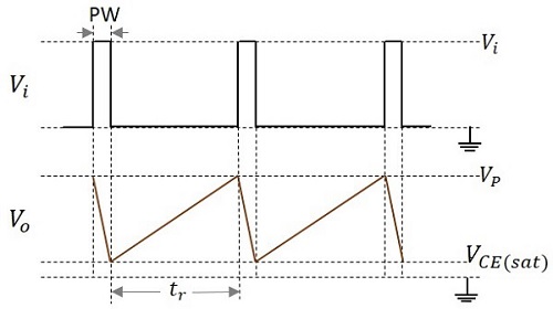
Pulse Circuits Quick Guide Tutorialspoint
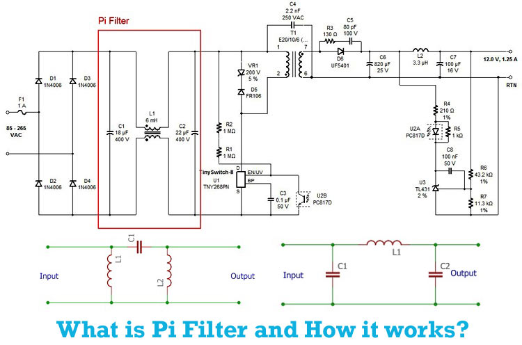
Pi Filter Overview Working Construction Application And Design Tips

Impulse Voltage Generator Marx Generator Circuit Diagram Working Principle And Applications
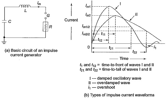
Generation Of Impulse Currents Waves Definition Circuit Diagram

Multistage Impulse Generator Circuits

National Grid Power Supply Electricity Explaining Use Of Transformers Formula Theory Calculations Pylons Versus Underground Cables Igcse Gcse Physics Revision Notes

Hv Module 3 Impulse Voltage Generation

Virtual Labs
Q Tbn And9gcqzo3xdoi2u7bn7kyyy0qtqc5seftwbufotmzcaklc Usqp Cau
5 The Marx Generator 10p Below Is The Schematic Chegg Com
Http Ethesis Nitrkl Ac In 6568 1 Vivek Verma 110ee0061 Thesis Pdf
Core Ac Uk Download Pdf Pdf

Class A Amplifier Is A Class A Transistor Amplifier
The Essentials Of Designing Mv Lv Single Line Diagrams Symbols Drawings Analysis Eep

Eurorack Diy Synthnerd

Procedure For Transformer Lightning Impulse Test Eep
How Electricity Flows Knowledge Bank Solar Schools
Http Ethesis Nitrkl Ac In 6326 1 E 53 Pdf
Ic 741 Op Amp Basics Characteristics Pin Configuration Applications
Geiger Counter Circuits

Astable Multivibrator And Astable Oscillator Circuit
Www Clemson Edu Cecas Departments Ece Document Resource Undergrad Lab Manuals Ece 212 Pdf

5 Marks D Draw The Basic Circuit Diagram Of The Multi Stage Impulse Generator Course Hero
How To Calculate And Draw A Single Line Diagram For The Power System Eep
Instrumentation Amplifier Using Opamp Circuit Diagram Working Construction

Generator Transformer An Overview Sciencedirect Topics

Hv Module 3 Impulse Voltage Generation
Generation Of High Voltages In The Lab Ac Dc Switching Lightning Impulse

Voltage Multiplier Voltage Doubler Voltage Tripler Voltage Quadrupler
High Voltage Transformers Electrical4u
Flasher Circuits
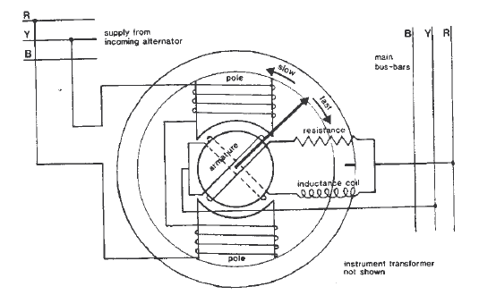
How To Synchronize Generators On A Ship

Impulse Voltage Generator Marx Generator Circuit Diagram Working Principle And Applications
The Essentials Of Designing Mv Lv Single Line Diagrams Symbols Drawings Analysis Eep

Cockroft Walton Voltage Multiplier Circuit Generation Of High Voltages And Currents
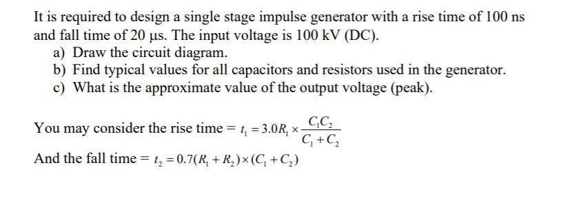
Solved It Is Required To Design A Single Stage Impulse Ge Chegg Com

Impulse Voltage Generator Marx Generator Circuit Diagram Working Principle And Applications
Op Amp Practical Considerations Operational Amplifiers Electronics Textbook
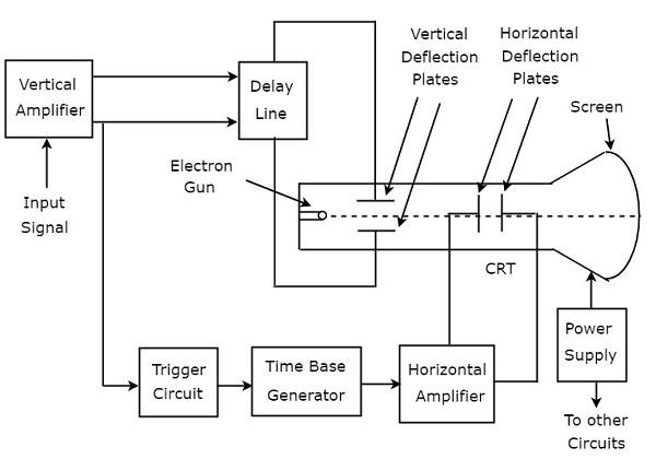
Basics Of Oscilloscopes Tutorialspoint

Multistage Impulse Generator Circuits

Impulse Voltage Generator Marx Generator Circuit Diagram Working Principle And Applications

Hivg 400kv 10kj Impulse Voltage Generator 800kv Range Himalayal High Voltage Test System Ac Dc Dielec
Pulse Circuits Quick Guide Tutorialspoint
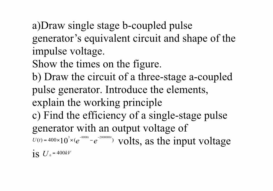
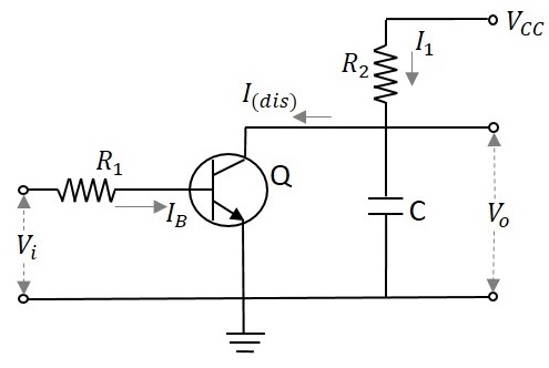
A Draw Single Stage B Coupled Pulse Generator S Eq Chegg Com

Rectification Of A Three Phase Supply Using Diodes
National Grid Power Supply Electricity Explaining Use Of Transformers Formula Theory Calculations Pylons Versus Underground Cables Igcse Gcse Physics Revision Notes
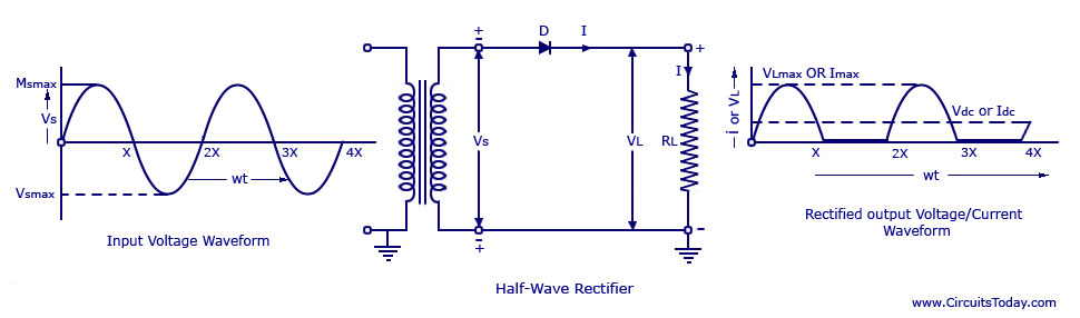
Half Wave Rectifier Circuit With Diagram Learn Operation Working


