N Stage Circuit Diagram Of Impulse Voltage Generator
Cockcroft Walton Generator Wikipedia

Impulse Voltage Generator Marx Generator Circuit Diagram Working Principle And Applications

Schematic Diagram Of Thermoelectric Generator Teg Composed Of P And Download Scientific Diagram
Uu Diva Portal Org Smash Get Diva2 Fulltext01 Pdf

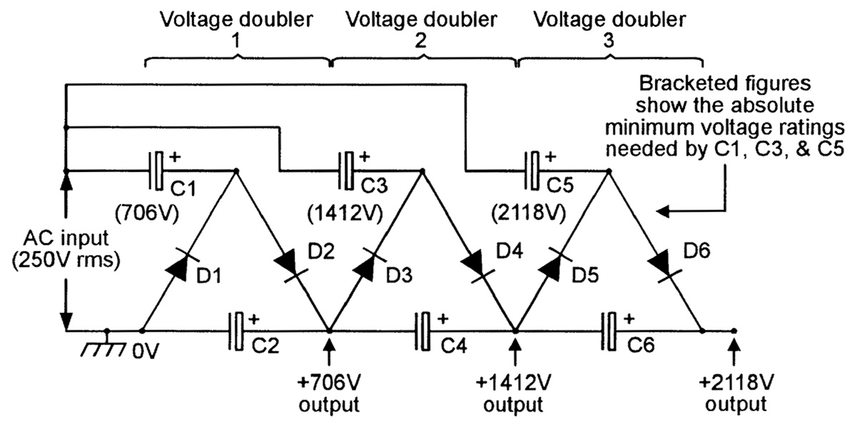
Voltage Multiplier Wikipedia
Www Irjet Net Archives V7 I6 Irjet V7i6263 Pdf
Single Stage Impulse Generator In order to understand the working of an Impulse generator, let stake a look at the circuit diagram of a singlestage impulse generator that is shown below The above circuit consists of two capacitors and two resistances.

N stage circuit diagram of impulse voltage generator. A UrRehman, N Khan 71 Figure 2 Circuit diagram of lightning impulse generator Figure 3 Standard impulse waveform 5 time is illustrated as 50 µs T 1 is the duration between 10% and 90% of the peak value of impulse and 2 is 50T % value of the peak value of impulse It is shown that lightning over voltage wave can be represented as double. In the figure, Square Wave Generator Circuit V 2 is the voltage across the capacitor, and V 1 is the node voltage at the positive terminal The current through opamp is zero because of the ideal characteristics of an opamp Let us consider node equations from the circuit diagram V 1 – V 0 / R 2 V 1 / R 1 = 0 V 1 1/R 2 1. Figure 2 is nstage voltage multiplier circuit Surge currents can be developed in rectifier circuits due to capacitive loading effects, the large stepup turn ratio.
1 Cascade the three previous opamp circuits to simulate the circuit shown in Figure 5 Print out the schematic for this circuit Figure 5 Function Generator 2 Using a transient analysis with the same parameters as in Part 1, plot the output of each opamp (on the same plot) You can do this by placing voltage markers on the output of each op. Draw a circuit diagram of simple voltage doublers An impulse generator has 10 stages with capacitors rated 015 μF and 150 kV per stage The load capacitor is 1000 pf Find the front and tail resistance to produce an impulse of 12 / 50 μs (approximate formula) GD Number of stage = solution C = Generator capacitance = / = μF. A reference generator implemented in a MOS technology integrated circuit comprises a current mirror device having three pairs of transistors connected so as to obtain a stable voltage at the mid point of its second arm This same generator also supplies a stable current.
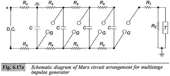
The Marx generator is a capacitive energy storage circuit which is charged to a given voltage level and then quickly discharged, delivering its energy quickly to a load at very high power levels A typical Marx circuit uses resistors to charge N capacitors in parallel to a voltage V,as shown in Figure 1 When triggered, the first switch. We have one battery charger circuit with current control,voltage control circuit using LM324 ,555,tip127 componentsIn this all com pain circuit of saw tooth, triangulate,pulse generation circuit We are drawn the avail circuit but we can’t identified the particular type of outputs. USA1 US11/362,742 USA USA1 US A1 US A1 US A1 US A US A US A US A1 US A1 US A1 Authority US United States Prior art keywords impulses differentiators impulse generator impulse transited Prior art date Legal status (The legal status is an assumption and is not a legal.
The JFET can be used as a fixedvalue current generator by either tying the gate to the source as in Figure 8(a), or by applying a fixed negative bias to the gate as in Figure 8(b) Alternatively, it can (when suitably biased) be used as a voltagetocurrent signal amplifier FIGURE 8 An nchannel JFET can be used as a constantcurrent generator. Generator StepUp Autotransformer Stepdown pads impulse 250/2500 ms •Induced Voltage (ac) •Applied Voltage (ac) Transformer Consulting Services Inc Transformer Design Insulation Coordination value of shortcircuit voltage), or in W related to. The basic circuit of Marx generator is shown in Figure 5 According to 6, there is a standard ratio of C1/C 2 for that particular Marx generator circuit, as depicted in Table 1 Calculation for one stage Marx generator Figure 5 Circuit for producing impulse voltage wave Note that, C1 = Stage capacitor C2 = Load capacitor R1 = Front resistor.
Figure 31 Circuit for impulse voltage generation 19 Figure 41 Schematic diagram of two stage standard Marx impulse voltage generator in NI Multisim software 19 Figure 42 Output impulse voltage waveform generated using second stage standard Marx impulse voltage generator circuit 21. Figure 45 A standard impulse wave (stage 4 using Standard Marx Impulse voltage circuit) Figure 46 Schematic Diagram of Single Stage Improved Marx Impulse Voltage Generator 21 Figure 47 A standard impulse wave (stage1 using Improved Marx Impulse voltage circuit) 22. A voltage to current (VI) converter accepts as an input a voltage Vin and gives an output current of a certain value In general the relationship between the input voltage and the output current is Iout =SVin (118) Where S is the sensitivity or gain of the VI converter Figure 7 shows a voltage to current converter using an opamp and a.
Figure 33 Composition of Hardware Circuit The sine wave generator consists of two parts The first half is the RC seriesparallel sine wave oscillator, the second half is the shift circuit, and finally the sine wave signal is added to the input pin of the SG3525 Figure 34 is a circuit diagram of the selected sinusoidal signal generating. Ac generator circuit breakers and external insulation (Ref IEC) (Ref ANSI) Insulation Withstand Voltages (1) Rated Rated Power Lightning Voltage Maximum Frequency Impulse Voltage 1minute, dry 12 x 50 µs wave (kV, rms) (kV, rms) (kV, rms) (kV, peak) Line Column 1 Column 2 Column 3 Column 4 1 72 5 60 2 12 5 28 75 3 175 5 / 15 38 95. (57) Summary Objective To provide an impulse voltage generator capable of generating an impulse voltage under stable conditions with a simple configuration A charging capacitor C charged with a desired high voltage (that is, a peak value of a desired impulse voltage) is connected in series with a plurality of thyristors 11 connected in series, a series resistor Rf, and a discharge.
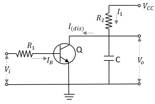
Let’s take a look at the figure below It’s a square wave generator circuit This circuit contains a 74LS00 Nand Gate integrated circuit Figure 1 Square Wave Generator Circuit Diagram Among this circuit diagram NAND gates 1, 2 and external RC time constant components form an oscillator circuit;. Figure 31 Circuit for impulse voltage generation 19 Figure 41 Schematic diagram of two stage standard Marx impulse voltage generator in NI Multisim software 19 Figure 42 Output impulse voltage waveform generated using second stage standard Marx impulse voltage generator circuit 21. The onestage equivalent, of an impulse voltage circuit with a capacitive load is shown in Fig 9 Resistances, which are used in Marx circuit, are non inductive All resistances have some small internal inductances, which leads to the inefficient outputs.
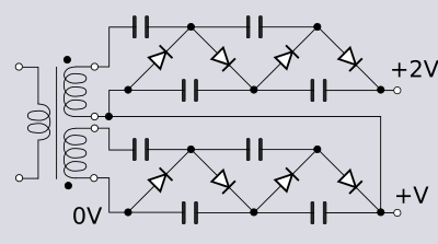
NAND gate 3 is a buffer output stage. Thus by measuring the voltage across the 1 st stage of voltage doubler and the last stage, we get the required high voltage Since the output is a very high voltage, it is not possible to measure it using a simple multimeter For this reason, a voltage divider circuit is used The voltage divider consists of 10 resistors connected in series. A singlephase, halfwave rectifier circuit is given the somewhat cryptic designation of 1Ph1W1P (1 phase, 1 way, 1 pulse), meaning that the AC supply voltage is singlephase, that current on each phase of the AC supply lines moves in only one direction (way), and that there is a single pulse of DC produced for every 360 o of electrical rotation.
Marx Impulse Generators for Higher powered Professional Research Available Systems from our Labs allow charging voltage from zero to full value with manual and 5 volt fire control Systems are complete and require 115 or 230 vac for operation Discharge shaping resistors are available per your requirement or use as is for fast discharge. An impulse voltage generator of n stages An impulse voltage generator without steeping circuit, operating without front resistors, can generate impulse voltages with front times down to about 100 ns Fig 725 a Simplified block diagram of a singlestage SI generator. I build an inverter using SG3524 in the oscillator stage and 8 IRF35 With a 112 transformer that is a 24v transformer after building the circuit it was giving me an output voltage of 175v but when I connect a load of 60watt the voltage begins to countdown.
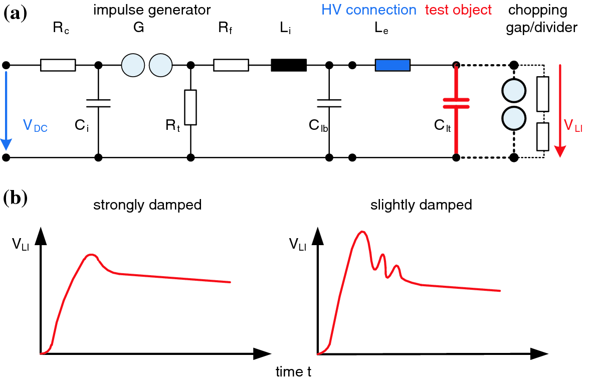
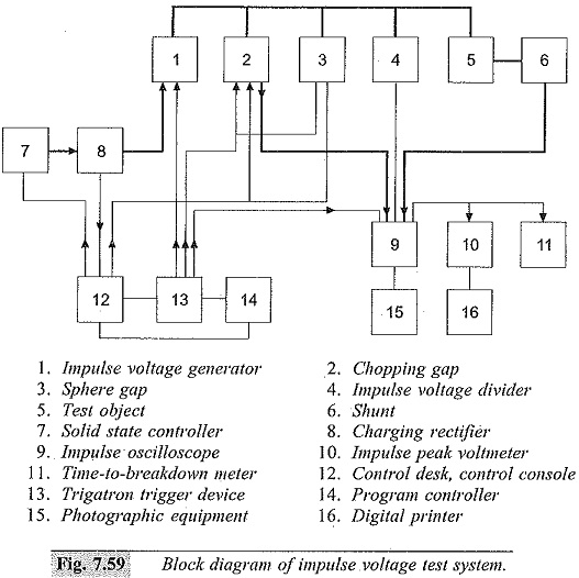
This is just a few minutes of a complete course Get full lessons & more subjects at http//wwwMathTutorDVDcomIn this lesson the student will learn what. As a representative dynamic PN generator, the schematic structure of the dynamic GaAs/Si generator is illustrated in Figure 1A The Ntype GaAs wafer was pressed on the Ptype Si substrate compactly with a 60 N force, which showed typical rectification behavior with a low leakage current density of 15 μA/cm 2 under the bias voltage of −3 V (Figure 1B). 27 a) Circuit diagram and b) a snapshot of the multiple chopping gap Courtesy of Manitoba Hydro HVTF a) High voltage winding diagram with CT connections and tap changer positions, b) Low voltage winding diagram, c) Plan view of the high voltage, low multistage impulse generator is simplified to a single stage generator The DUT’s.
Let’s take a look at the figure below It’s a square wave generator circuit This circuit contains a 74LS00 Nand Gate integrated circuit Figure 1 Square Wave Generator Circuit Diagram Among this circuit diagram NAND gates 1, 2 and external RC time constant components form an oscillator circuit;. NAND gate 3 is a buffer output stage. An impulse generator circuit accordi ng to the input data of the table II was implemented a s an energizer prototype, using the design procedure presented (Fig 12).
Type Impulse Generator The goal was to estimate the stray capacitance and insert that capacitance into the simulation circuit to effectively produce an output similar to that of the generator An actual threestage impulse generator was used as the base Several different levels of impulse voltage were tested, and the output waveforms were. For the circuit Fig 321(a) the output voltage is thus given by the expression Figure 321Singlestage impulse generator circuits (a) and (b) C1 discharge capacitance C2 load capacitance R1 front or damping resistance R2 discharge resistance. The present invention achieves constant voltage at radio frequencies to drive a constant voltage to constant current converter, by employing a tightly coupled dc feedback loop to control the voltage via a transformer to the drain of a FET operated as a Class C amplifier in the saturated mode whereby among other advantages, the amplifier can withstand, without damage, very high VSWRs.
In the basic circuit, a source may be dc or ac, and its internal resistance (R i) or generator output impedance (Z g) drives a load resistance (R L) or impedance (Z L) (Fig 1) R L = R i or Z L = Z g. Functioning at 1 KHz or higher frequency, the pulse generator demonstrated below drives a voltage doubler circuit furnishing a negative potential getting close to that of the positive input supply Using a 10 volt input, an output of around 9 VDC has been measured into a ,000 ohm load. So how does it work The circuit shows a half wave voltage doubler During the negative half cycle of the sinusoidal input waveform, diode D1 is forward biased and conducts charging up the pump capacitor, C1 to the peak value of the input voltage, (Vp)Because there is no return path for capacitor C1 to discharge into, it remains fully charged acting as a storage device in series with the.
High Voltage Engineering Lab Lab 6 Generation and Measurement of impulse voltages 1 Objective The objective of this lab is consisting of the following tasks 1 Generation of full lighting impulse (LI12/50) voltage using single stage circuit of type B, as per IEC 2 Generation switching impulse (SI) voltage using single stage circuit as per IEC. Figure 2 shows the fundamental circuit of high voltage lightning impulse generator Each stage of Marx generator is consists of resistors, capacitors and spark gaps, is in parallel combination during charging When switch turn on, capacitor becomes in serial and then charged capacitor added The theoretical output voltage is given by (1). Note Separately excited DC generators are rarely used in practice 2 Self Excited DC Generator These are generators in which the field winding is excited by the output of the generator itself As described before – there are three types of selfexcited dc generators – they are 1) Series 2) Shunt and 3) Compound a.
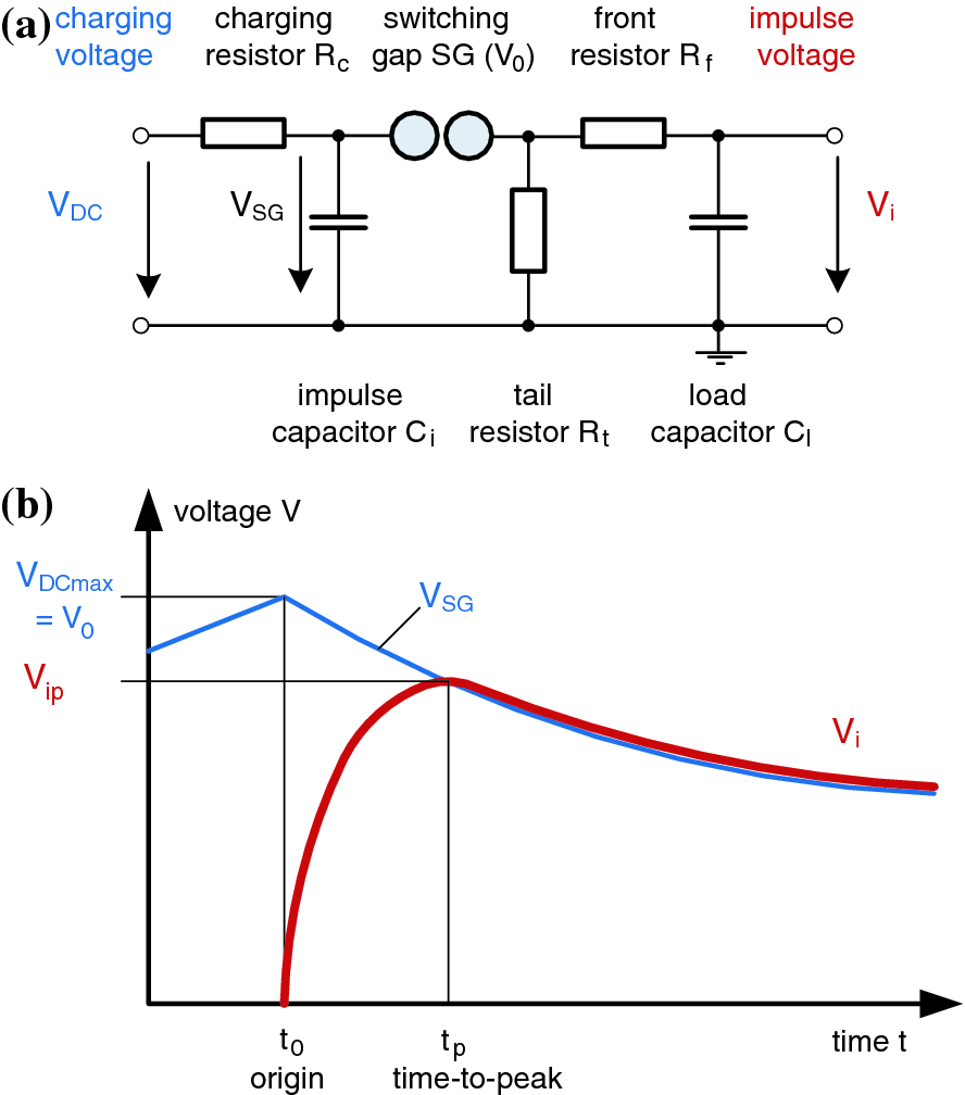
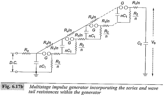
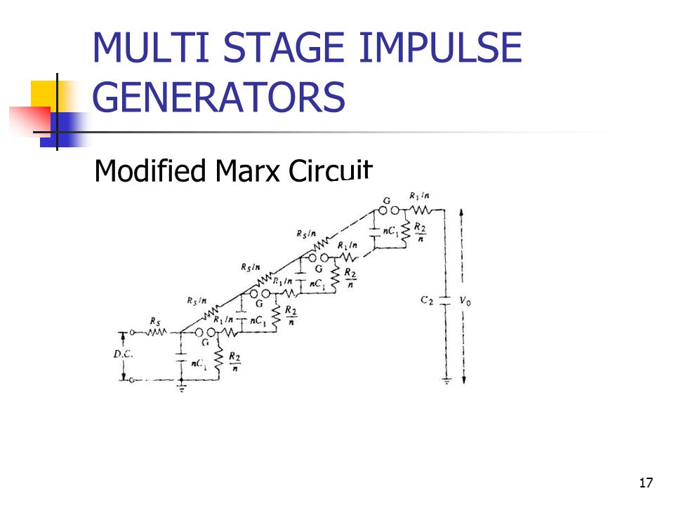
Multistage Impulse Voltage generator is used in high power equipment testing and also in the experimental transmission line and aviation object’s The basic principle of the Multistage impulse voltage generator is the charging x number of capacitors in parallel & discharge them in series stack MIVG's consist of a N number of stack where each. The onestage equivalent, of an impulse voltage circuit with a capacitive load is shown in Fig 9 Resistances, which are used in Marx circuit, are non inductive All resistances have some small internal inductances, which leads to the inefficient outputs. Impulse voltage generatorAn impulse generator essentially consists of a capacitor which is charged to the required voltage and discharged through a circuit The circuit parameters can be adjusted to give an impulse voltage of the desired shape Basic circuit of a single stage impulse generator is shown in Fig 1, where the capacitor C s is.
Core Ac Uk Download Pdf Pdf
Tests With High Lightning And Switching Impulse Voltages Springerlink

Standard 1 2 X 50ms Wave Shape T2 T1 Download Scientific Diagram
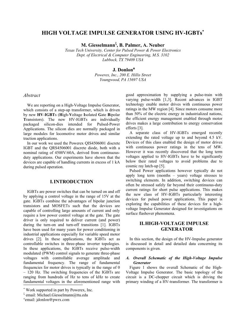
Pdf High Voltage Impulse Generator Using Hv Igbts

Series Resonant Circuit Generation Of High Voltages And Currents
Ijarcce Com Upload 17 May 17 Ijarcce 118 Pdf
Www Irjet Net Archives V7 I6 Irjet V7i6263 Pdf

Procedure For Transformer Lightning Impulse Test Eep
Multistage Impulse Generator Circuit Marx Circuit Components

Impulse Voltage Generator Marx Generator Circuit Diagram Working Principle And Applications
Www Mitmuzaffarpur Org Wp Content Uploads 18 11 Ee 7th Sem High Voltage Pdf
Pdf Simulation Of Impulse Voltage Generator And Impulse Testing Of Insulator Using Matlab Simulink
Tests With High Lightning And Switching Impulse Voltages Springerlink

Hv Module 3 Impulse Voltage Generation
Generation Of Impulse Currents Waves Definition Circuit Diagram
Design And Fabrication Of A High Voltage Lightning Impulse Generator
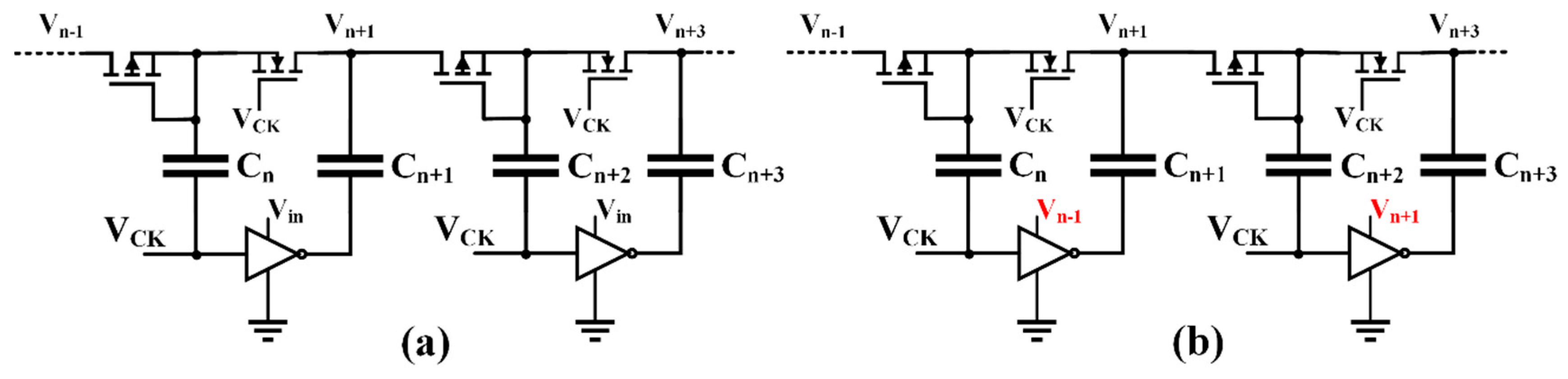
Electronics Free Full Text 4t Analog Mos Control High Voltage High Frequency Hvhf Plasma Switching Power Supply For Water Purification In Industrial Applications Html
Www Mitmuzaffarpur Org Wp Content Uploads 18 11 Ee 7th Sem High Voltage Pdf
Ijarcce Com Upload 17 May 17 Ijarcce 118 Pdf

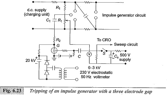
Impulse Voltage Generator Circuits

Hv Module 3 Impulse Voltage Generation

Figure 2 From Multi Purpose Low Cost Dc High Voltage Generator 60kv Output Using Cockcroft Walton Voltage Multiplier Circuit Semantic Scholar
Www Iitk Ac In Npsc Papers Npsc10 6010 Pdf
Voltage Multiplier Wikipedia

Impulse Voltage Generator Circuits
Academicjournals Org Article Article Dwived and daigvane Pdf
Impulse Test Of Transformer Electrical4u
Www Irjet Net Archives V7 I6 Irjet V7i6263 Pdf
Testing Transformers Part 1

Class A Amplifier Is A Class A Transistor Amplifier

Figure 2 From High Voltage High Frequency Marx Bank Type Pulse Generator Using Integrated Power Semiconductor Half Bridges Semantic Scholar
How To Reduce Distortion In High Voltage High Frequency Signal Generation For Awgs Analog Technical Articles Ti E2e Support Forums

Impulse Voltage Generator Marx Generator Circuit Diagram Working Principle And Applications
Multistage Impulse Generator Circuit Marx Circuit Components
Q Tbn And9gcrvkyanc2oyayzglt5yekxok0pvkzxxp Qmebj6qm6x9f4lxky6 Usqp Cau

Hv Module 3 Impulse Voltage Generation
Http Www Iaea Org Inis Collection Nclcollectionstore Public 45 102 Pdf R 1
High And Low Voltage Cut Off With Time Delay Circuit Diagrams Schematics Electronic Projects

Multistage Impulse Generator Circuits

Procedure For Transformer Lightning Impulse Test Eep
Academicjournals Org Article Article Dwived and daigvane Pdf

Multistage Impulse Generator Circuits
Core Ac Uk Download Pdf Pdf

Hv Module 3 Impulse Voltage Generation

Ee 2353 High Voltage Engineering Ppt Video Online Download

Pdf Design And Simulation Of A High Voltage Dc Hvdc Generator

Impulse Voltage Generator Circuits
Q Tbn And9gcsedc Askvsxpphkuxqfojvz35zwtxwtlbkdslwsm Wzvcpwt8s Usqp Cau
Core Ac Uk Download Pdf Pdf

High Voltage Amplifier Uses Simplified Circuit Edn
Www Scielo Br Pdf Reng V33n2 2446 4740 Reng 33 2 144 Pdf
Deepblue Lib Umich Edu Bitstream Handle 27 42 Master thesis changqi you Format check V3 Pdf Sequence 1

Impulse Voltage Generator Marx Generator Circuit Diagram Working Principle And Applications
Q Tbn And9gctzruknkqlsxwjzbt Lftrmbwwkbi4 H2qhgvxldz8kk Yzpqmk Usqp Cau
Www Mitmuzaffarpur Org Wp Content Uploads 18 11 Ee 7th Sem High Voltage Pdf

Hv Module 3 Impulse Voltage Generation
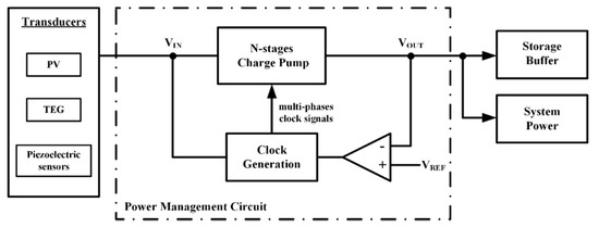
Electronics Free Full Text A Review Of Charge Pump Topologies For The Power Management Of Iot Nodes Html
National Grid Power Supply Electricity Explaining Use Of Transformers Formula Theory Calculations Pylons Versus Underground Cables Igcse Gcse Physics Revision Notes

Hv Module 3 Impulse Voltage Generation

Charge Pump Wikipedia
Testing Transformers Part 1
Dc Voltage Converter Circuits Nuts Volts Magazine
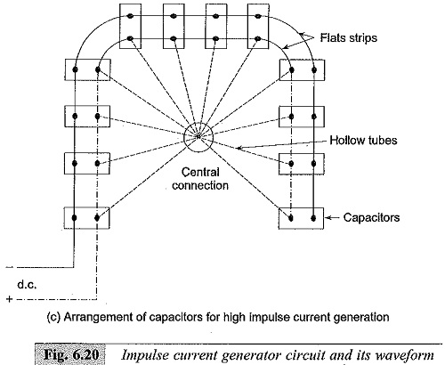
Generation Of Impulse Currents Waves Definition Circuit Diagram

C W Voltage Multiplier Circuit Download Scientific Diagram

National Grid Power Supply Electricity Explaining Use Of Transformers Formula Theory Calculations Pylons Versus Underground Cables Igcse Gcse Physics Revision Notes
Http Www Onlinejournal In Ijirv3i4 264 Pdf

555 Circuits Part 2 Voltage Multiplication
Q Tbn And9gctv Vk8msywhtjceryhzzdkklomqci Dpsy7eklstf5ggardvw1 Usqp Cau

Impulse Test Of Transformer Electrical4u

Virtual Labs

Basic Circuit Of Single Stage Impulse Generator Download Scientific Diagram
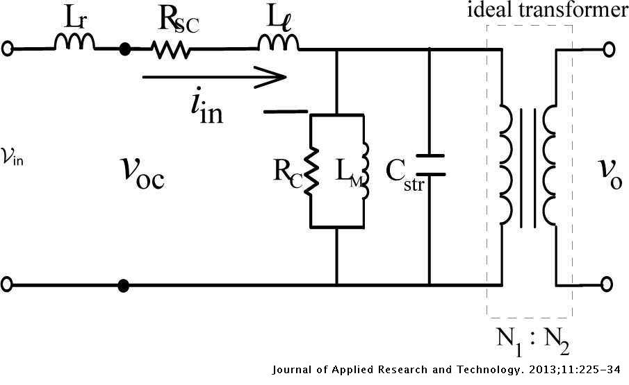
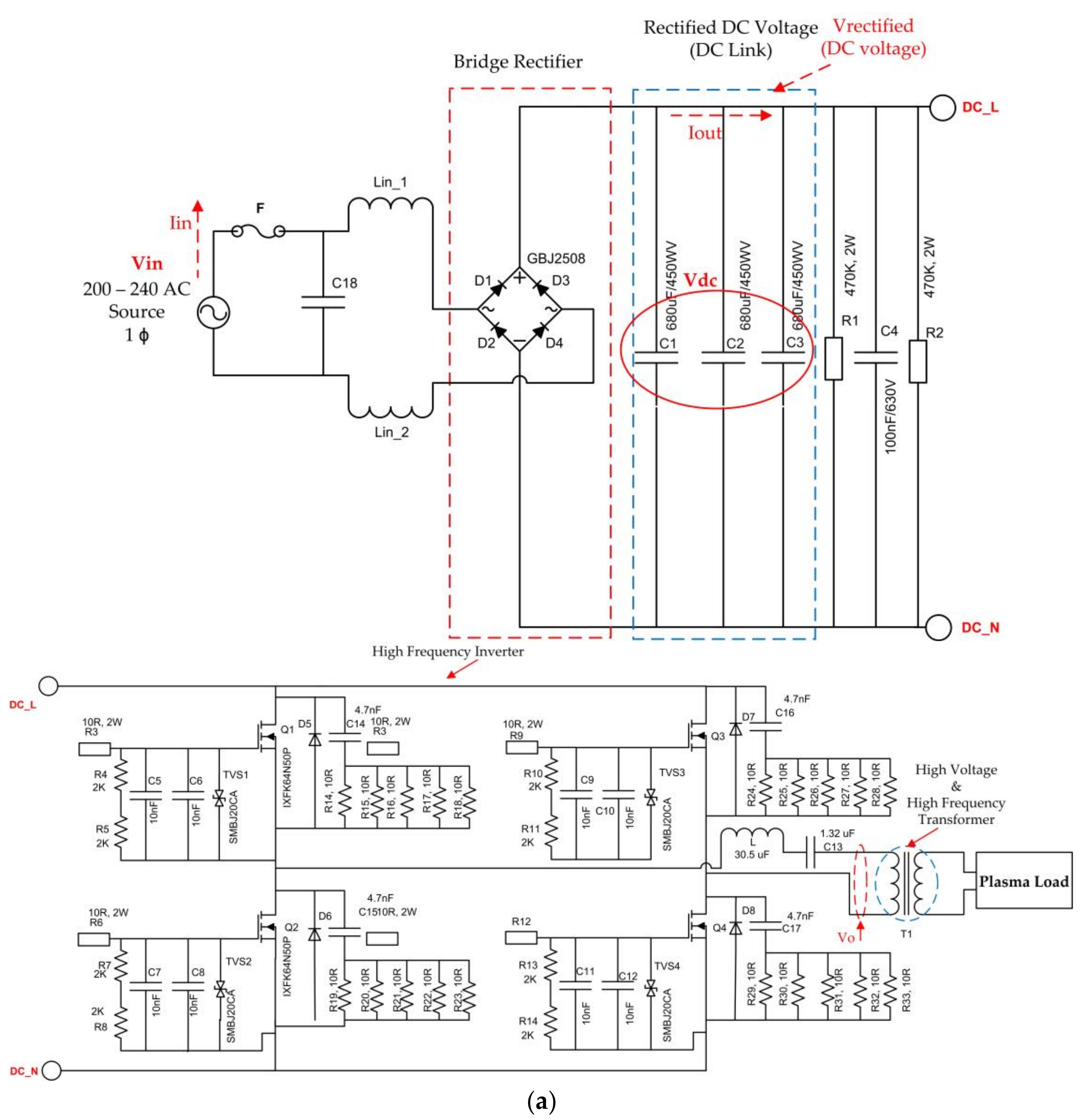
Design Of Plasma Generator Driven By High Frequency High Voltage Power Supply Journal Of Applied Research And Technology Jart
Www Iitk Ac In Npsc Papers Npsc10 6010 Pdf
Electronics Free Full Text A Review Of Charge Pump Topologies For The Power Management Of Iot Nodes Html

Basic Circuit Of Single Stage Impulse Generator Download Scientific Diagram
Multistage Impulse Generator Circuit Marx Circuit Components

Voltage Multiplier And Voltage Doubler Circuit

High Voltage Energy Harvesters Intechopen

Half Wave Cockroft Walton Voltage Multiplier With N Stages And Download Scientific Diagram
Marx Generator Wikipedia
Electronics Free Full Text 4t Analog Mos Control High Voltage High Frequency Hvhf Plasma Switching Power Supply For Water Purification In Industrial Applications Html

Basic Circuit Of Single Stage Impulse Generator Download Scientific Diagram

Marx Generator Wikipedia
Pulse Circuits Quick Guide Tutorialspoint

Impulse Test Of Transformer Electrical4u
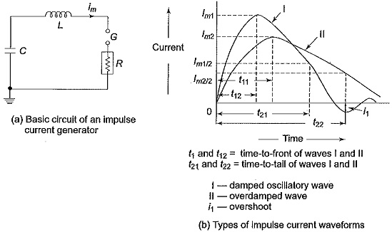
Generation Of Impulse Currents Waves Definition Circuit Diagram

Hv Module 3 Impulse Voltage Generation
Inis Iaea Org Collection Nclcollectionstore Public 45 102 Pdf

Impulse Voltage Generator Marx Generator Circuit Diagram Working Principle And Applications

Impulse Voltage Generator Circuits

Design Of Plasma Generator Driven By High Frequency High Voltage Power Supply Sciencedirect

Figure 1 From High Voltage High Frequency Marx Bank Type Pulse Generator Using Integrated Power Semiconductor Half Bridges Semantic Scholar
Ee 2353 High Voltage Engineering Ppt Video Online Download
Railgun Circuit Diagram Madscience
Http Citeseerx Ist Psu Edu Viewdoc Download Doi 10 1 1 132 4514 Rep Rep1 Type Pdf

Transient Over Voltages Due To Lightning And Switching Action Cause Steep Build Up Of Voltage On Transmission Lines And Other Electrical Power Apparatus Experimental Investigations Show That These Waves Have A Rise Time Of 0 5 To 10 µs And Decay Time To 50

Cockroft Walton Voltage Multiplier Circuit Generation Of High Voltages And Currents

Cockroft Walton Voltage Multiplier Circuit Generation Of High Voltages And Currents


